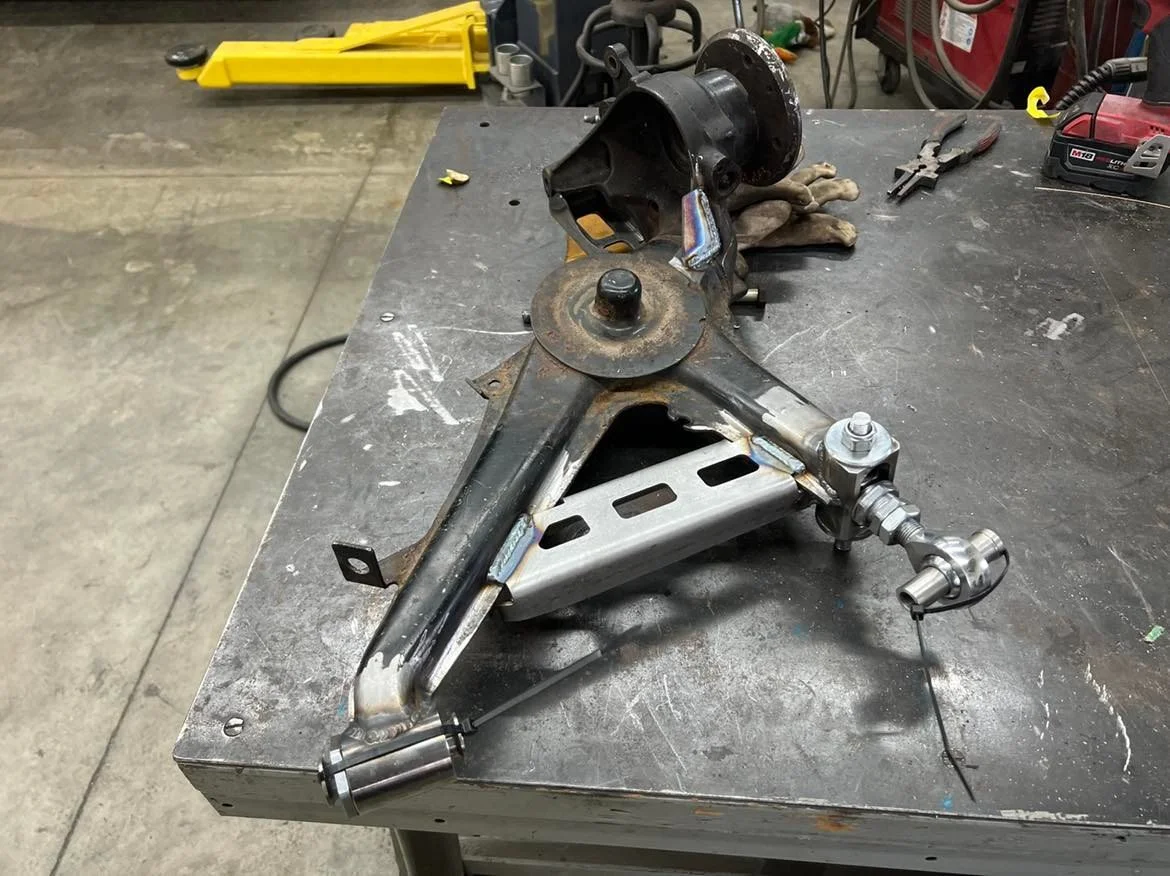
E30 MRT Dual Adjuster Rear Trailing Arm Installation Guide
From the factory, BMW designed the E30 with a non adjustable rear trailing arm, which works great within the original geometry. While competing in the DTM series with the E30 M3, BMW used rear trailing arms that had camber and toe adjustability to allow the cars to be setup for different track conditions.
MRT Engineering, a reputable parts manufacturer out of Finland, has recreated a kit inspired by BMW’s DTM trailing arms. These arms give consumers the ability to add camber and toe adjustment to their standard E30 rear control arm. Many other companies offer a solution to this problem where the subframe is modified to allow minor adjustment, but in my opinion is the incorrect route as this solution does not allow enough adjustment and has been known for moving with aggressive driving.
Along with the adjustment kit, MRT suggests adding additional reinforcements to strengthen the rear trailing arm. Therefore, a reinforcement package was created to compliment the adjustment kit, which can be purchased here.
The installation of the MRT double adjustment kit is a very intensive process but, with the right tools and knowledge, the process is actually very simple. When installing the adjustment kit, one of the biggest pieces to the puzzle is creating a jig that maintains the geometry. The jig I created was designed around an extra subframe I had at my shop. This allowed me to use the original pickup point geometry designed by BMW.
With the control arms bolted to the subframe, additional tubing and sheet metal was added to the subframe to locate the caliper and strut mounting points from the original trailing arm. Since this added structure needed to be very strong and rigid, I decided to make it using 1.50 x .095 DOM tubing scraps and 11 ga. steel plate with extra gussets. This combination creates a very simple, but effective, jig that allows the consumer to remove the additional structure at the end and use the subframe.
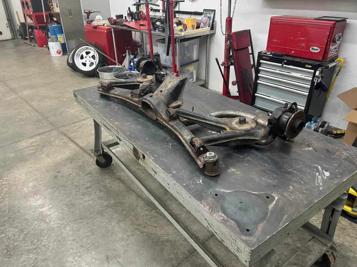
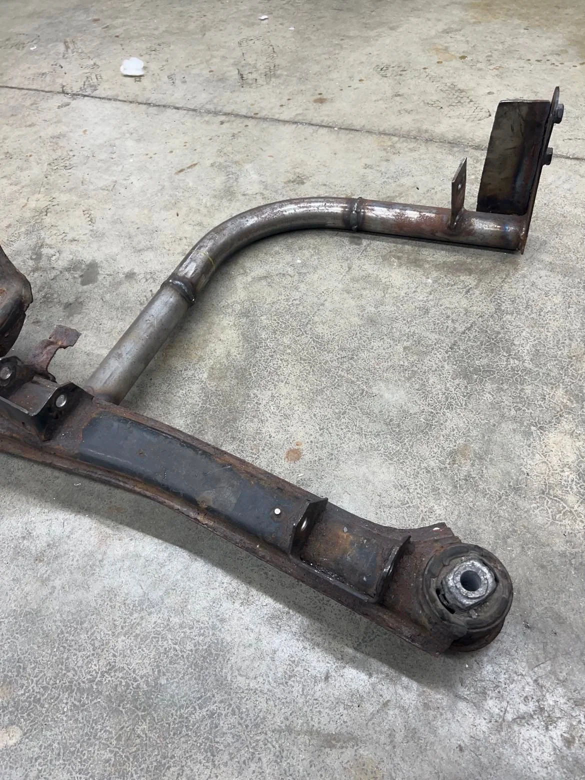
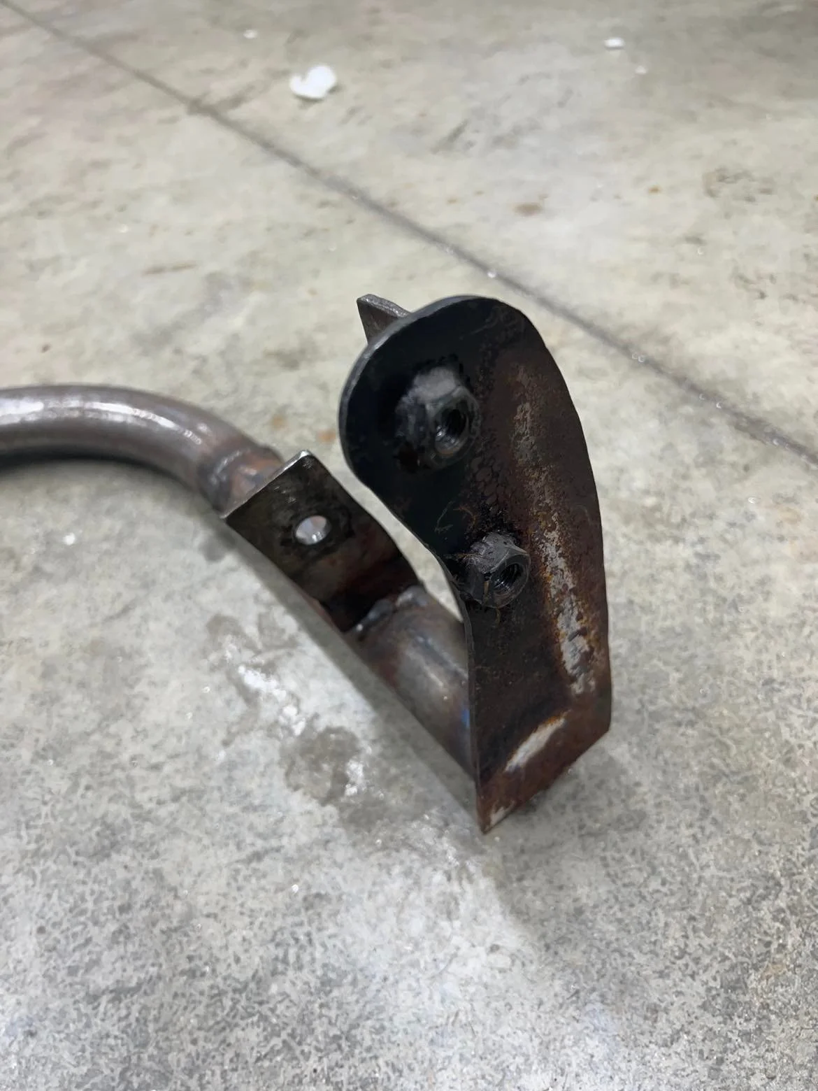

With the jig complete, the trailing arm modification can began. To start, the inside spherical joint will be installed first. While it may seem more exciting to get the dual adjuster done, it is smart to install the inside spherical joint while you still have the fixed original bushing that can be bolted in place with the jig.
I have found the best method for preparing the trailing arm start by grabbing a cut-off wheel on a grinder and cutting the original bushing sleeve in half where it is welded to the control arm.
Once the outside half is removed, exchange the cut-off wheel for a flap disc and grind the cut edge until the seam between the trailing arm and the bushing sleeve is exposed. Once the seam is noticeable, mark a line connecting the two seams as shown below. Use a carbide bit to create a groove where the marked lines are seen. As you grind, the groove will break through the bushing sleeve and the center portion can be removed.
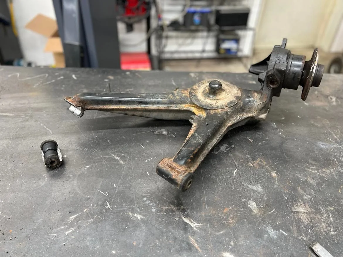

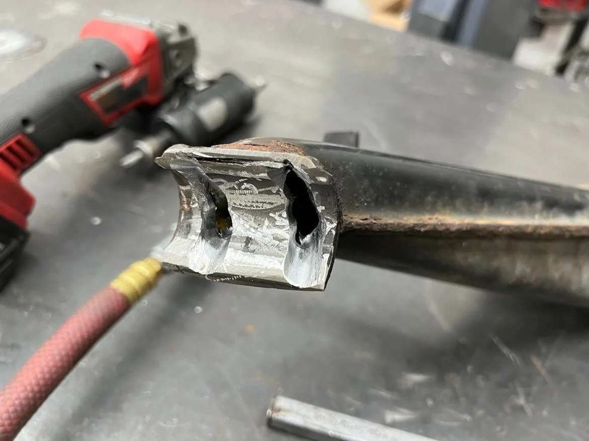

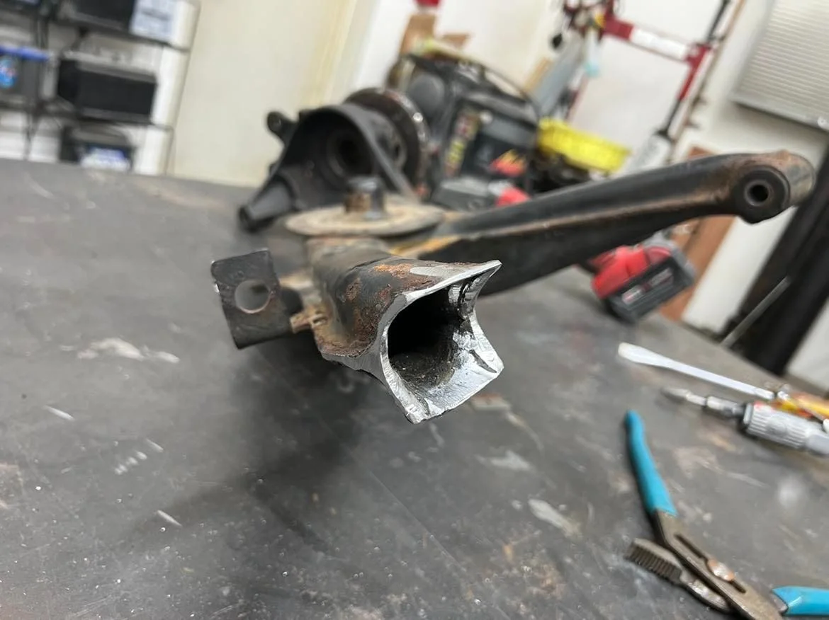
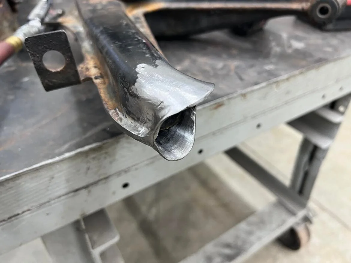
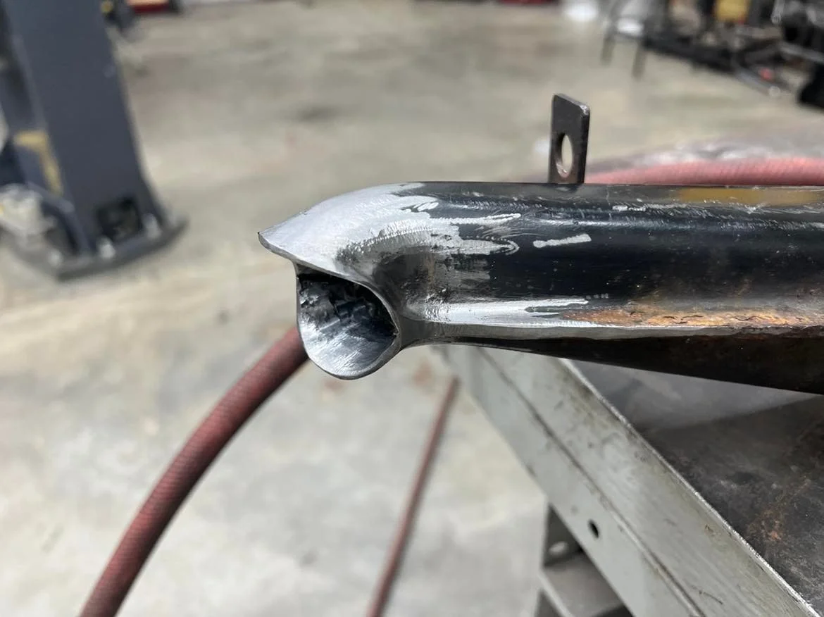
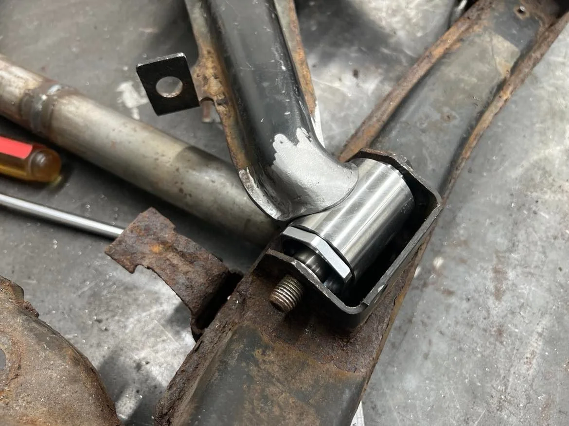
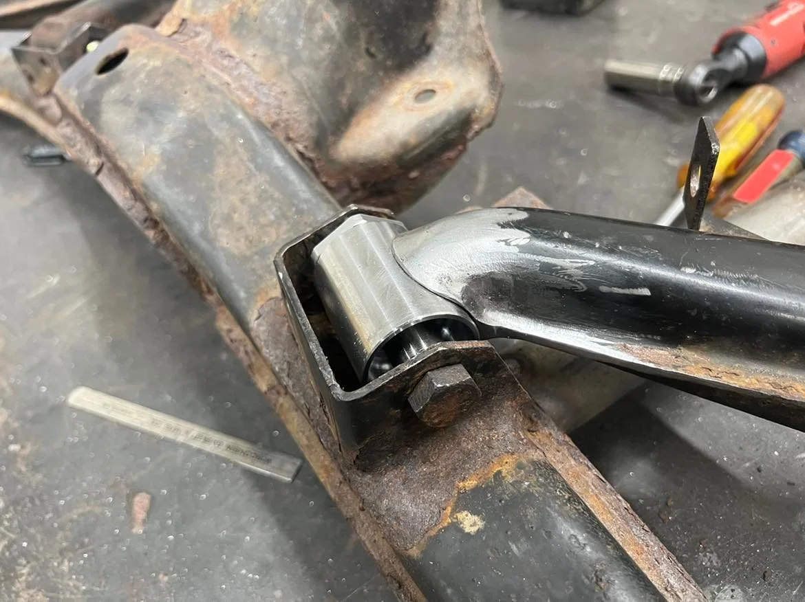
Once the bushing sleeve is removed, extra material will remain which needs to be removed for the spherical joint to be installed in the correct position. To reference this, the pictures below shows how the spherical joint is positioned with the minimal amount of material removed.

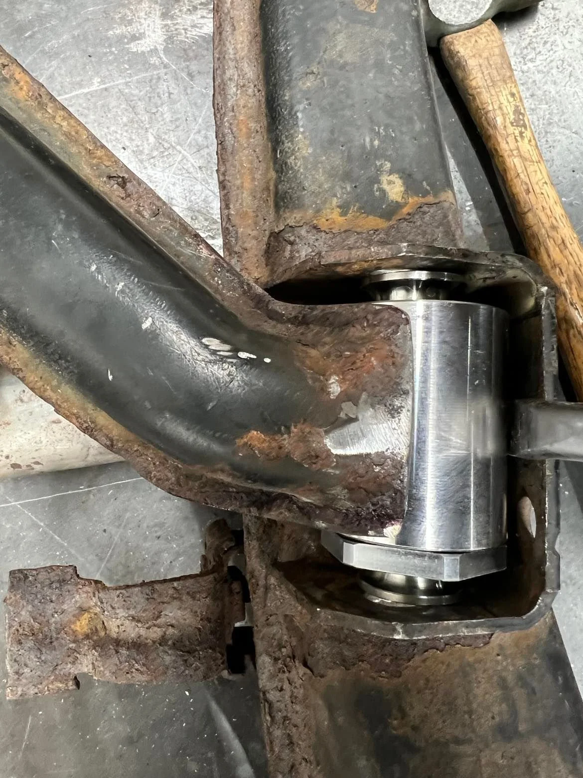
As shown, there needs to be material removed to allow the spherical joint to move backwards to line up with the holes and to narrow up width on both sides. This will allow a good surface for welding. Without a good surface to weld to on the side, there is a high chance of bleeding over the edge, which can create big problems especially on the threaded side.
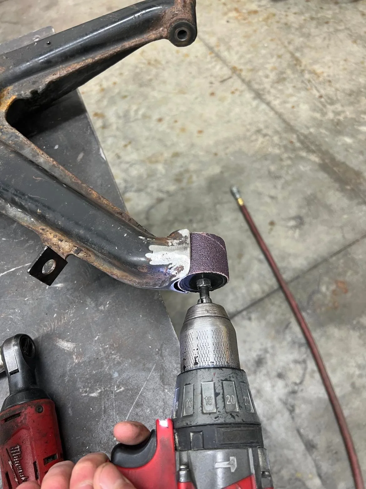
To remove this extra material, I have found it is best to remove the bulk of the material with your carbide bit and flap disk. Once the bulk of the material is removed, a 1.50” sanding drum can be used to shape a profile to exactly match the spherical joint. Once the spherical joint is in the correct position, a flap disc is used to remove all thin edges and clean off the surface to prepare for welding. It is always a good idea to finish cleaning the surface with a wire wheel to remove any hard to reach areas.
The spherical joint should fit into the control arm without any large gaps around it and the control, and be able to have the bolt side into the jig without any major force. Once this is complete, everything can be tack welded into place. I like to have two secure tacks on the upper side while bolted in the jig. Then, remove the control arm from the jig and add two more on the bottom side.


With the inside spherical joint securely tack welded into place, we can move over to the dual adjuster side. To start, you need to set the adjuster to the correct position. I like to set the toe adjustment to where each adjuster portion is showing 7mm of thread. MRT states that at the most each portion can be showing 15mm of thread. With setting each portion at 7mm, it allows you to adjust in either direction. This also moves the adjustment nuts further out, which makes it easier/possible to tighten or loosen the locking nuts to make adjustments.
To reference this adjuster setup to the control arm, use a 1.50” hole saw drill to drill into the control arm 86mm from the weld seam, as shown below. This 86mm distance will allow a few mm of extra material incase the hole is drilled at an angle or a slightly incorrect position. Once completely through with the hole saw, the remaining material can be cut with a cut-off wheel.

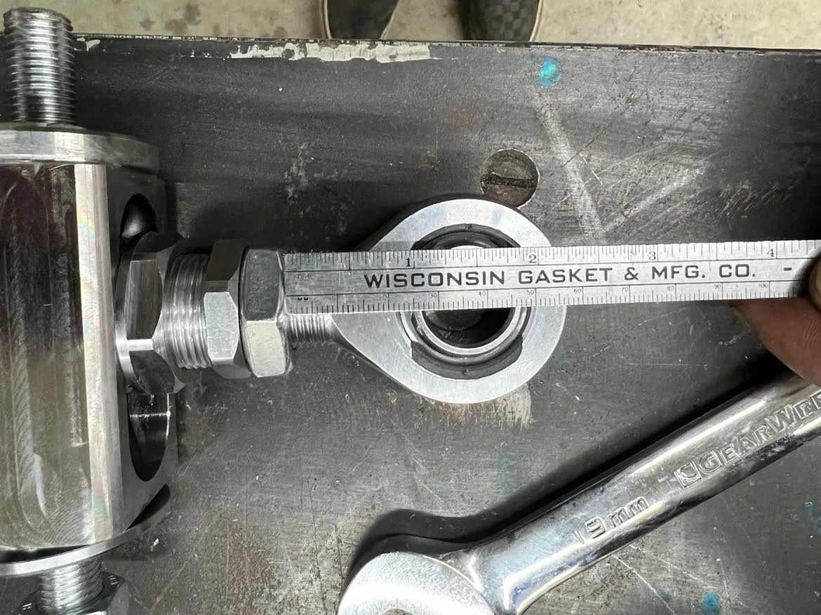
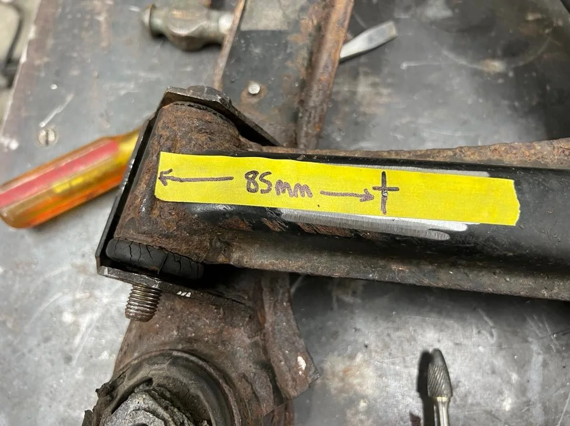
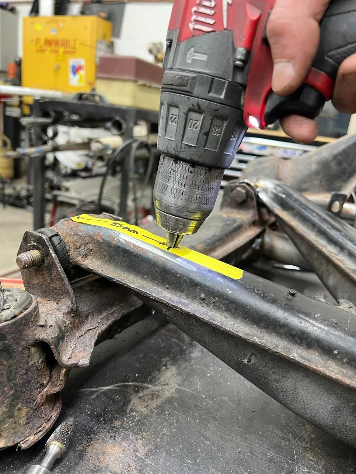
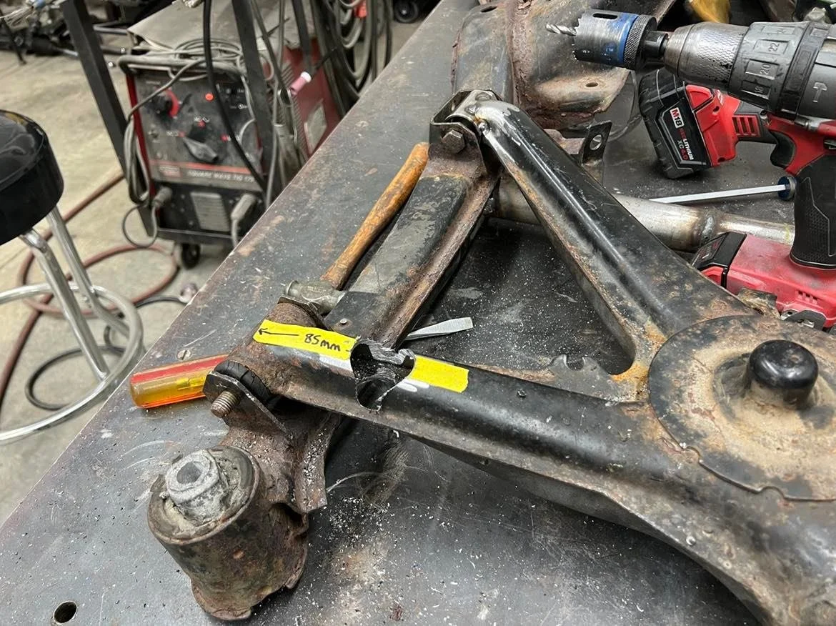

The mount can now be removed from the jig and the double adjuster test fit to see what areas will need to be modified. Once again, the carbide bit and 1.50” sanding drum are perfect tools for any material removal/fine tuning. Once the double adjuster is in the correct position, use a flap disc to remove all thin edges and clean off the surface to prepare for welding. It is always a good idea to finish cleaning the surface with a wire wheel to remove any hard to reach areas.
For setting the camber adjustment to get the most amount of positive camber possible, it is ideal to offset the double adjuster body up from the bottom as far as possible while leaving enough of a surface for welding. The heim joint should be centered in between the two mounting surfaces. Once all of these steps are complete, everything can be tack welded into place. I like to have the secure tacks on the upper side while bolted in the jig. Then, remove the control arm from the jig and add two more on the bottom side.
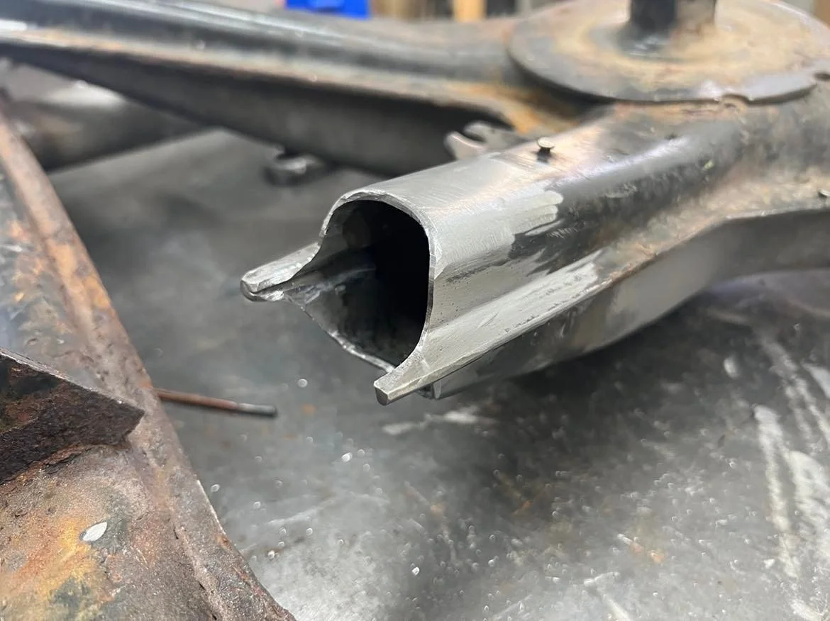
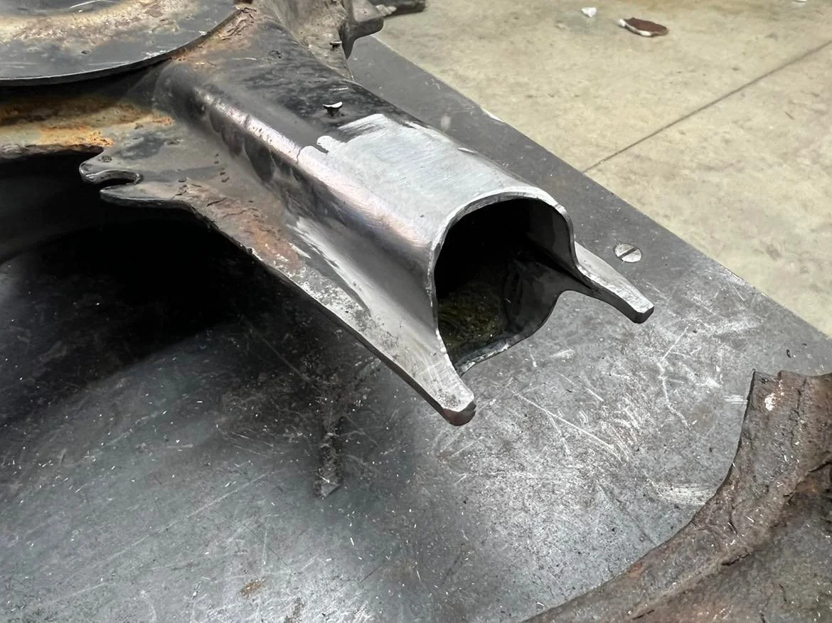


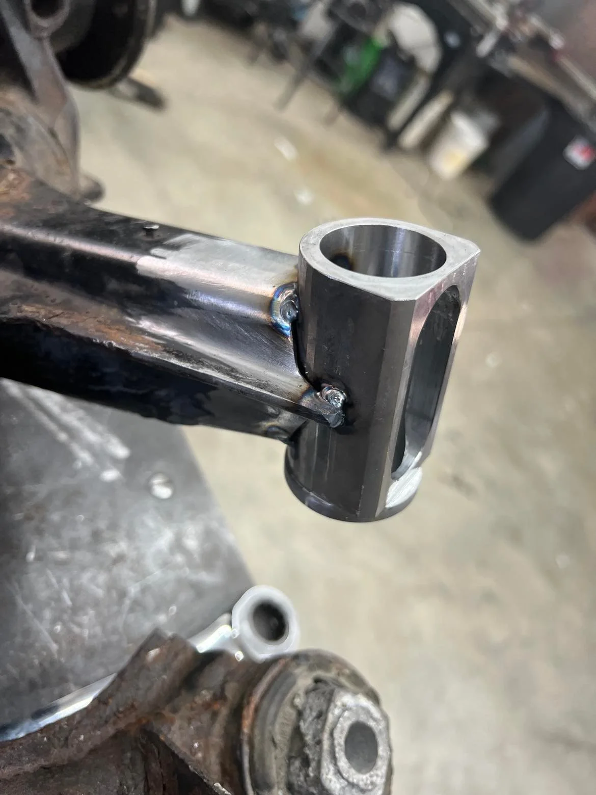

With everything tacked into place, the spherical bearing, threaded cap, and double adjuster can be removed from the control arm. Once removed, the arms should be ready to weld. The housings are machined with tight bearing tolerances, and the extreme amount of heat introduced by the welding process increased the probability of deformation/warping.
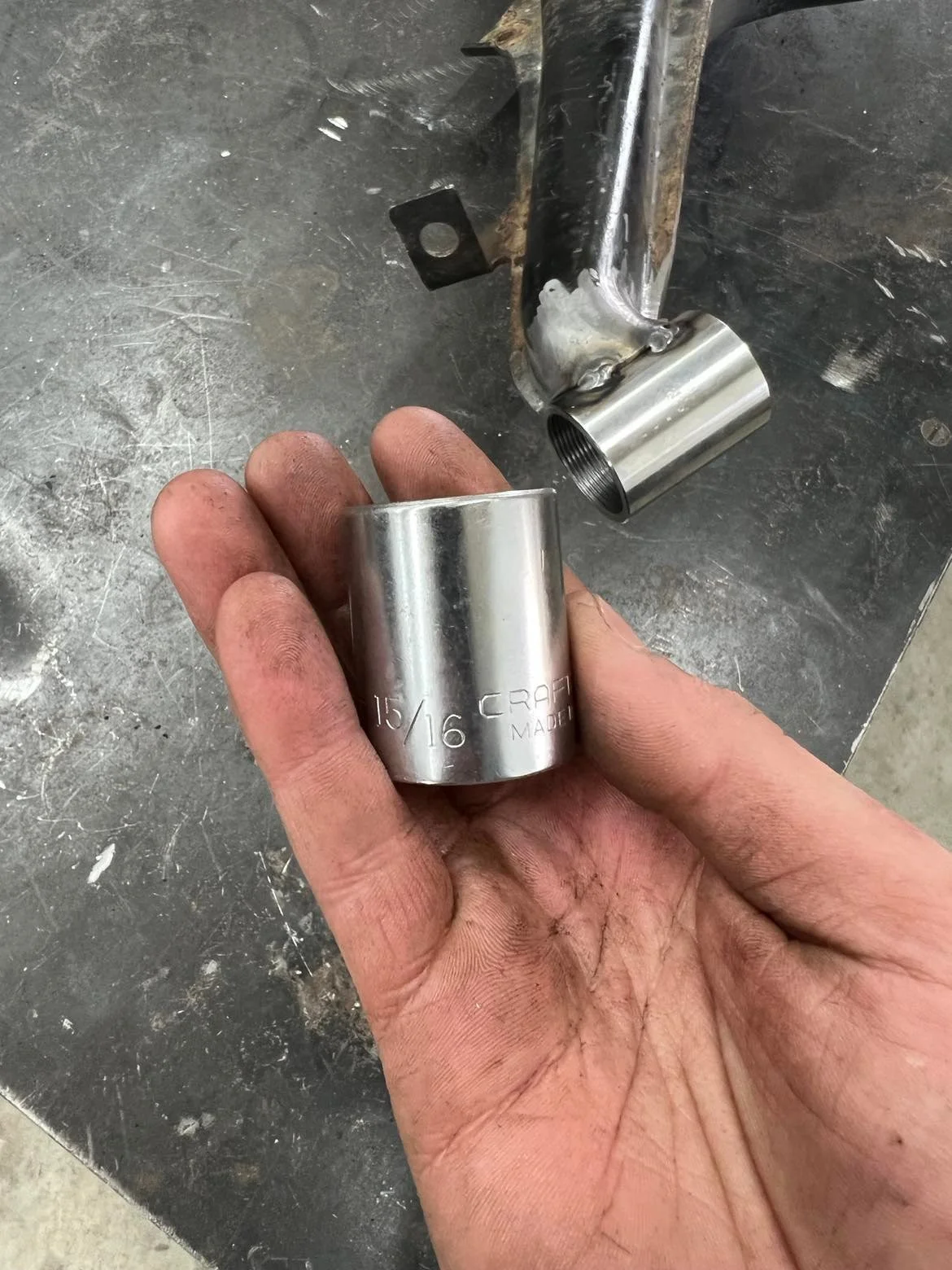
To prevent warping, I found a 15/16” Craftsman socket fits perfectly in the spherical bearing housing and a 7/8” Craftsman socket fits perfectly in the double adjuster housing. Using random hardware laying around the shop, the sockets are bolted into the housings to keep them in position while rotating and moving to weld completely around the adjuster.
For best results and heat control, the housings are tig welded to the control arms. Take your time and work in small sections, switching between sides to prevent overheating one specific area.


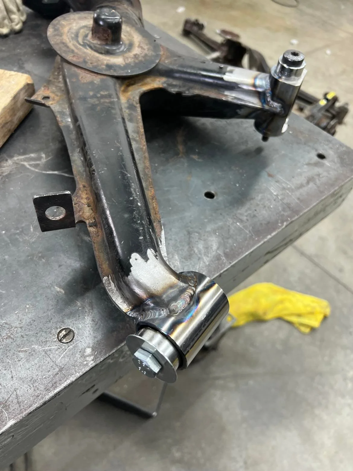


After welding, let the control arm air cool. Then, remove the sockets and reinstall the bearings and adjusters. With everything reinstalled, the control arms can be prepared to add the additional reinforcement. With a flap disc and wire wheel, remove any coating from the areas needed for welding.
Test fit the reinforcement panels to see if any adjustments are needed. Once fitment is confirmed, the corners on the strut mount reinforcement can be welded and cleaned up with a flap disc.
Before welding any of the reinforcements to the control arm, bolt the control arm back into the jig.
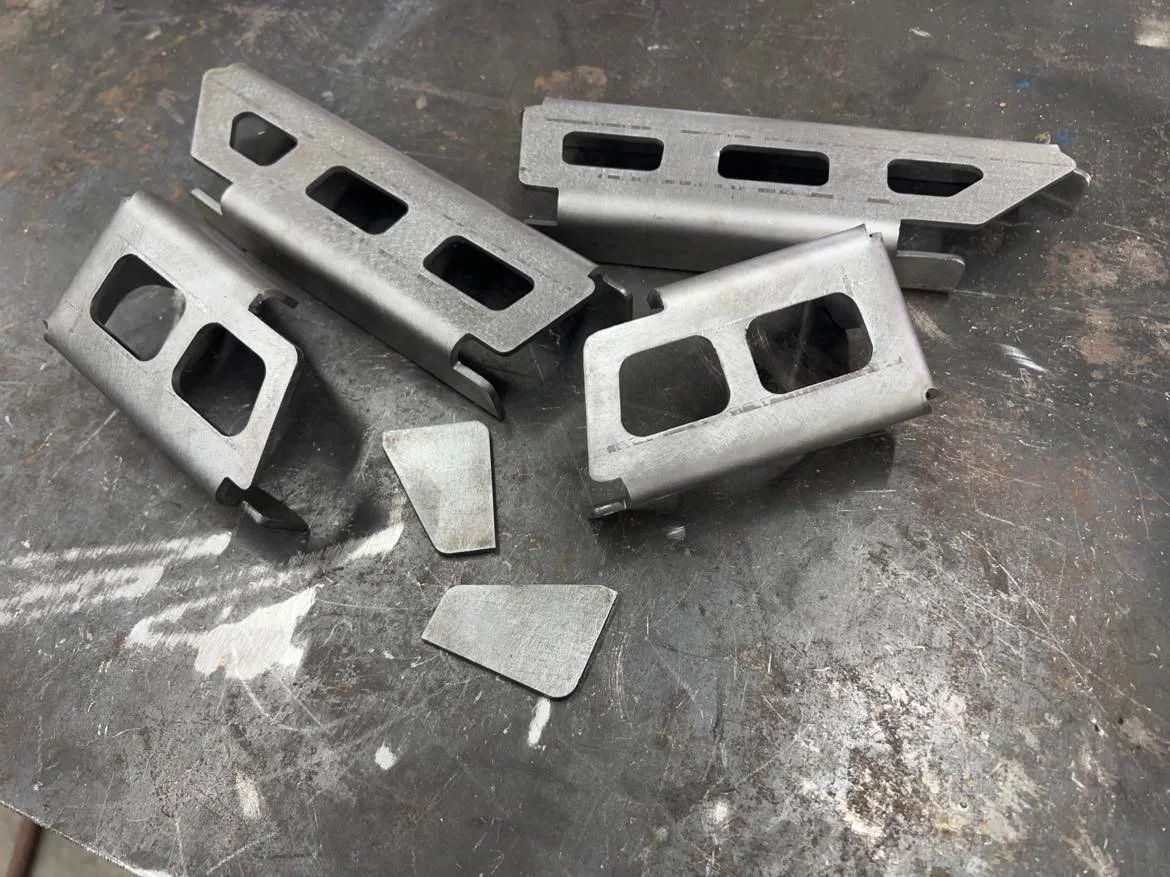
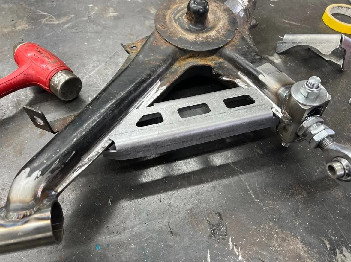
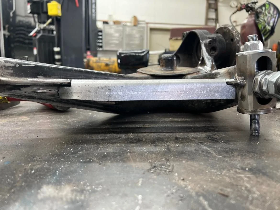


With the control arm bolted back into the jig, the reinforcement can be welded to the control arms as much as possible and removed to finish welding any areas that were not accessible while they were bolted into the jig,
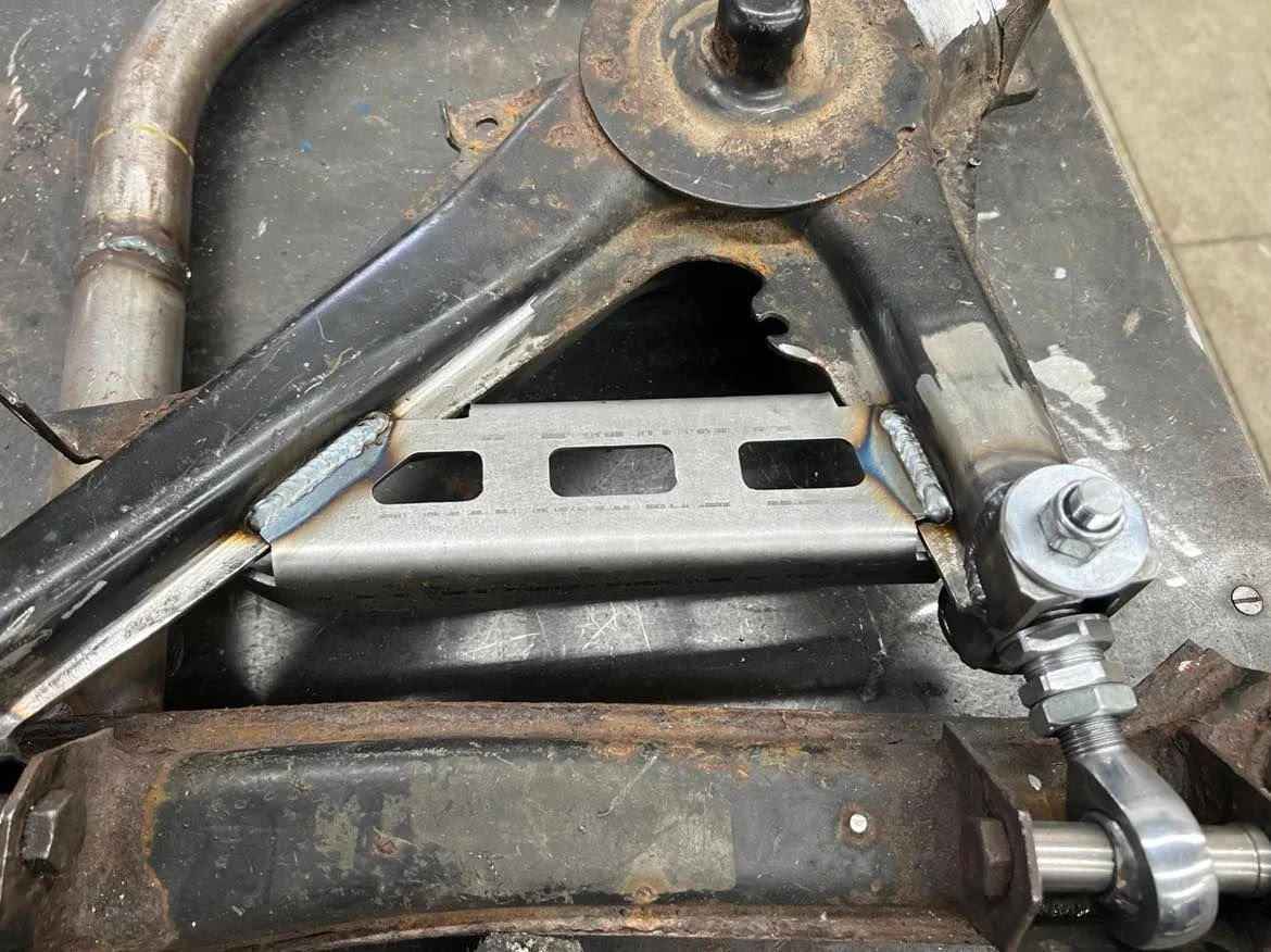

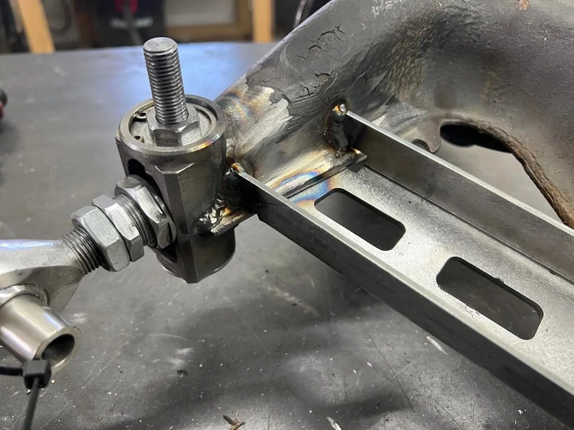
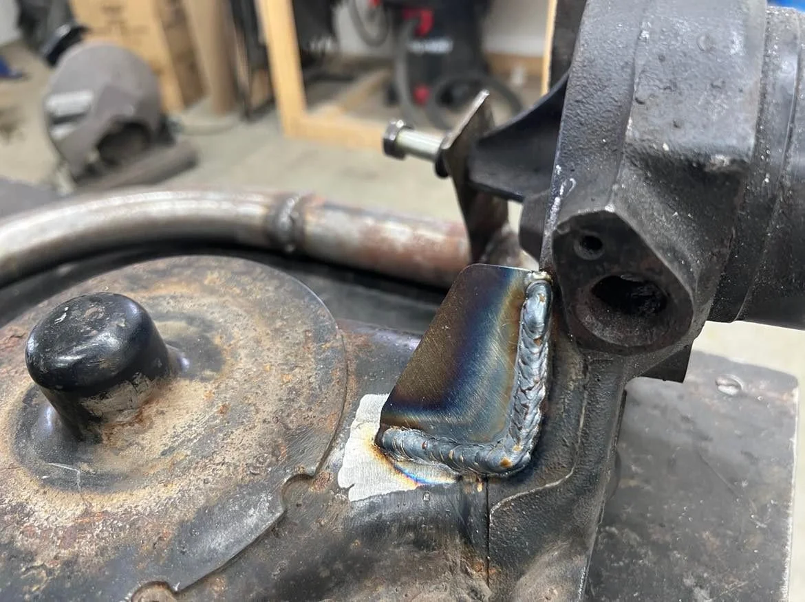

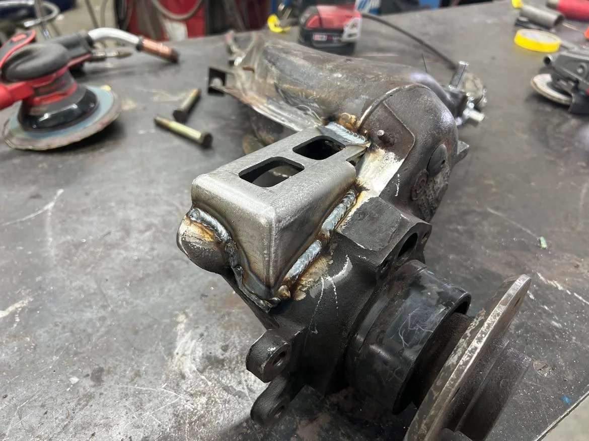

You have officially converted your standard E30 control arms with the MRT rear trailing arm dual adjuster kit. The last step is to cover all of the bare metal to prevent rusting. There are a lot of options for doing so including paint, powder coating, etc.
If you made it this far, thank you for reading. Any feedback or suggestions on current or new projects is always appreciated!
