E92 M5X Engine Swap Mount Arms
In the 1990’s, BMW released the M5X series of engines, and over time it has proven itself to be an amazing powerplant when paired with a turbo charger. The M5X engine also comes with a great community and aftermarket support surrounding it.
Growing to love this engine in my E30 over the years, I knew it would be a great powerplant to move into the E92 chassis. After finding a clean e92 rolling chassis, I decided the best way to complete the engine swap was to take the dive into investing into a 3D scanner to further my skillset. After months of research, numerous opinions, and saving my pennies, I purchased an Einscan Pro HD 3D scanner.
Once the scanner arrived, I immediately began scanning the engine, transmission, and engine bay.
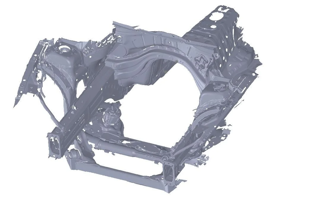
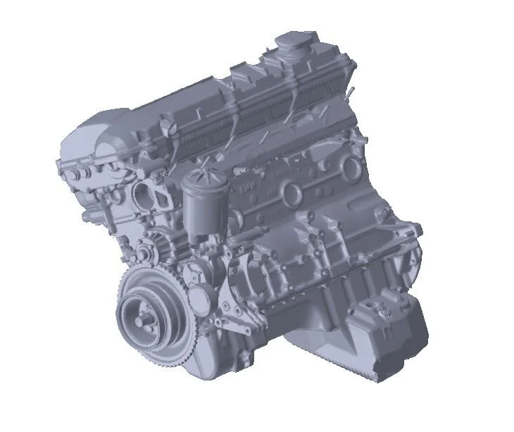
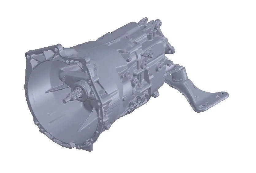
With the individual scans complete, data needs to be manipulated to create features that allow everything to be fitted together. These features include crank centerline, engine tilt angle, transmission mounting faces, input shaft centerline, engine mount stud positions, and engine bay/transmission tunnel midplane. For example, using this data, I determined that the original E36 oil pan interferes with the E92 subframe. Luckily, after discussing this issue with a few friends, I decided to use an oil pan from E39. Without creating specific reference features, the scan data can only be used as a visual reference.
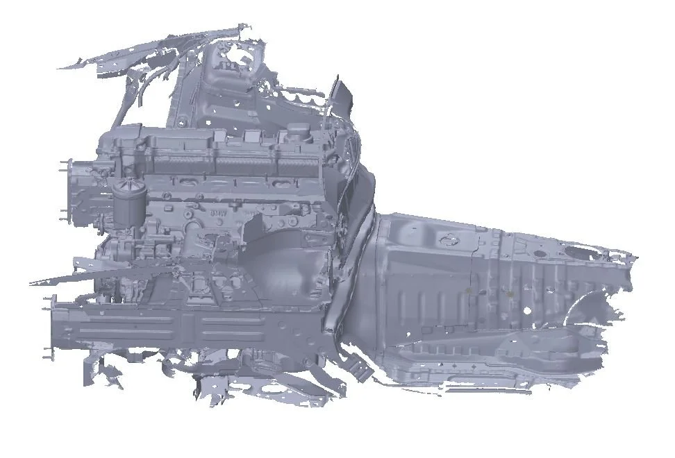
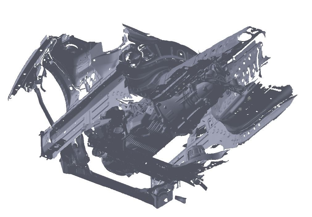
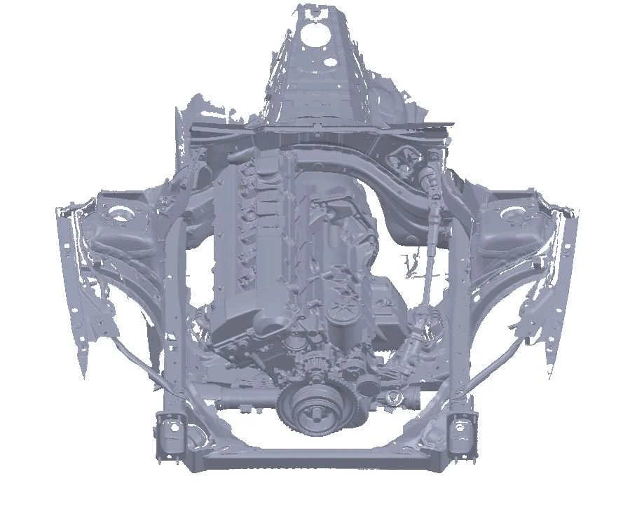
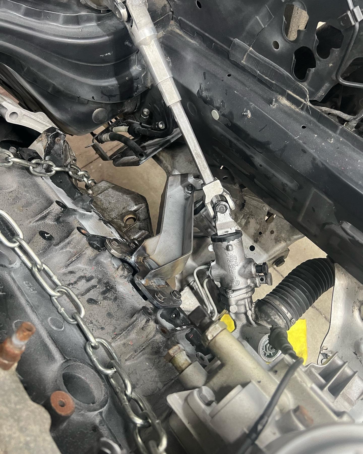
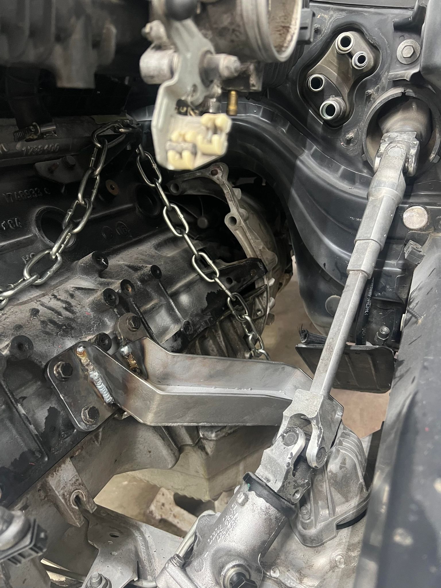
Once the engine and transmission are positioned, the motor mount design process began. The 3D scans allow the design to account for items such as steering shaft clearance. The mounts are designed with a sheet metal construction, which allows the manufacturing process to be completed in-house. Once the sheet metal mount design is complete, a jig is designed to aid in fabricating parts that match the design.
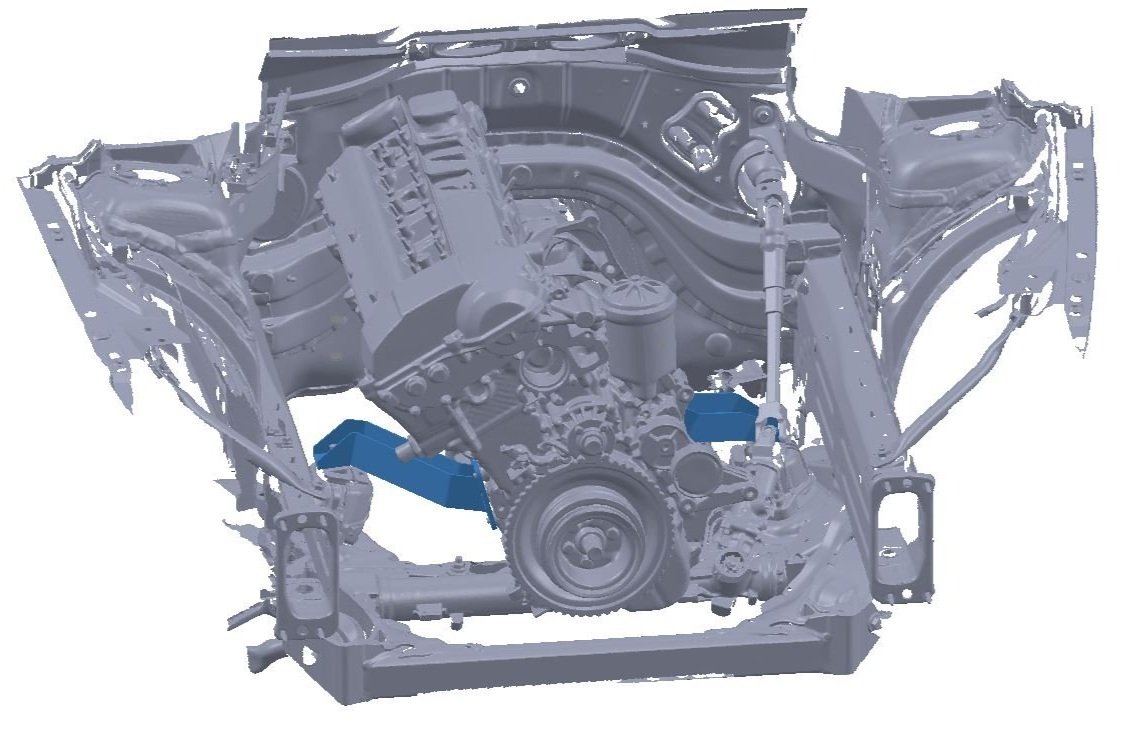

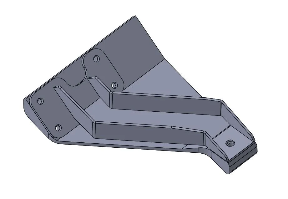

Using this design, each individual flat pattern is extracted, programed, and cut on the plasma table. Once cut, the sheet metal components are bent on the press brake and fitted together while the jigs are created using a 3D printer.
The channeled portion is welded before being fitted into the 3D printed jig with the mounting flange. Welding as much as possible beforehand reduces the chance of the part warping. This is an important step because the parts can only be tacked together inside the jig. This will prevent the jig from melting. After finishing the welds, the part is fitted back in the jig to double check fitment.
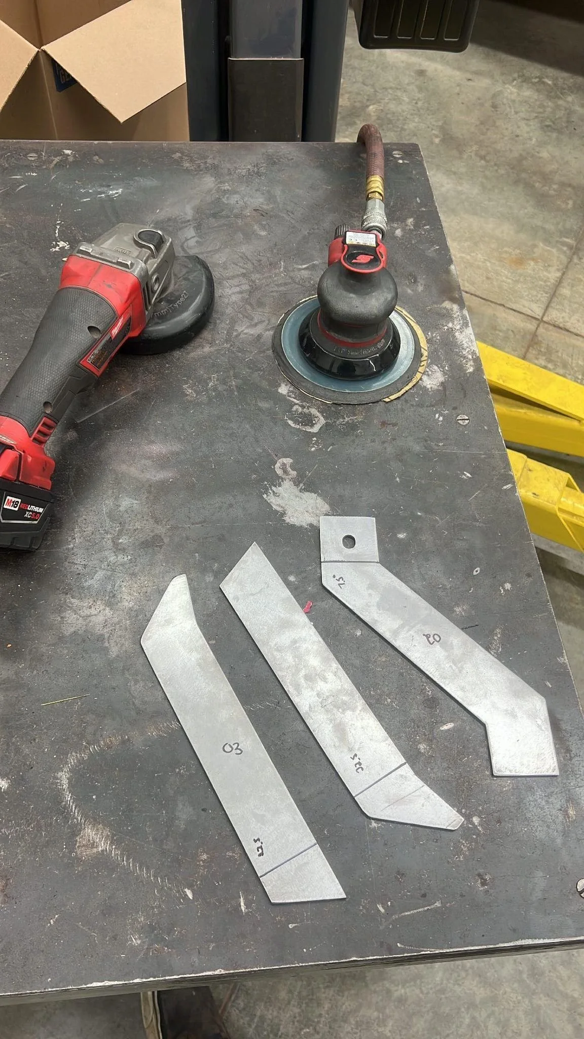
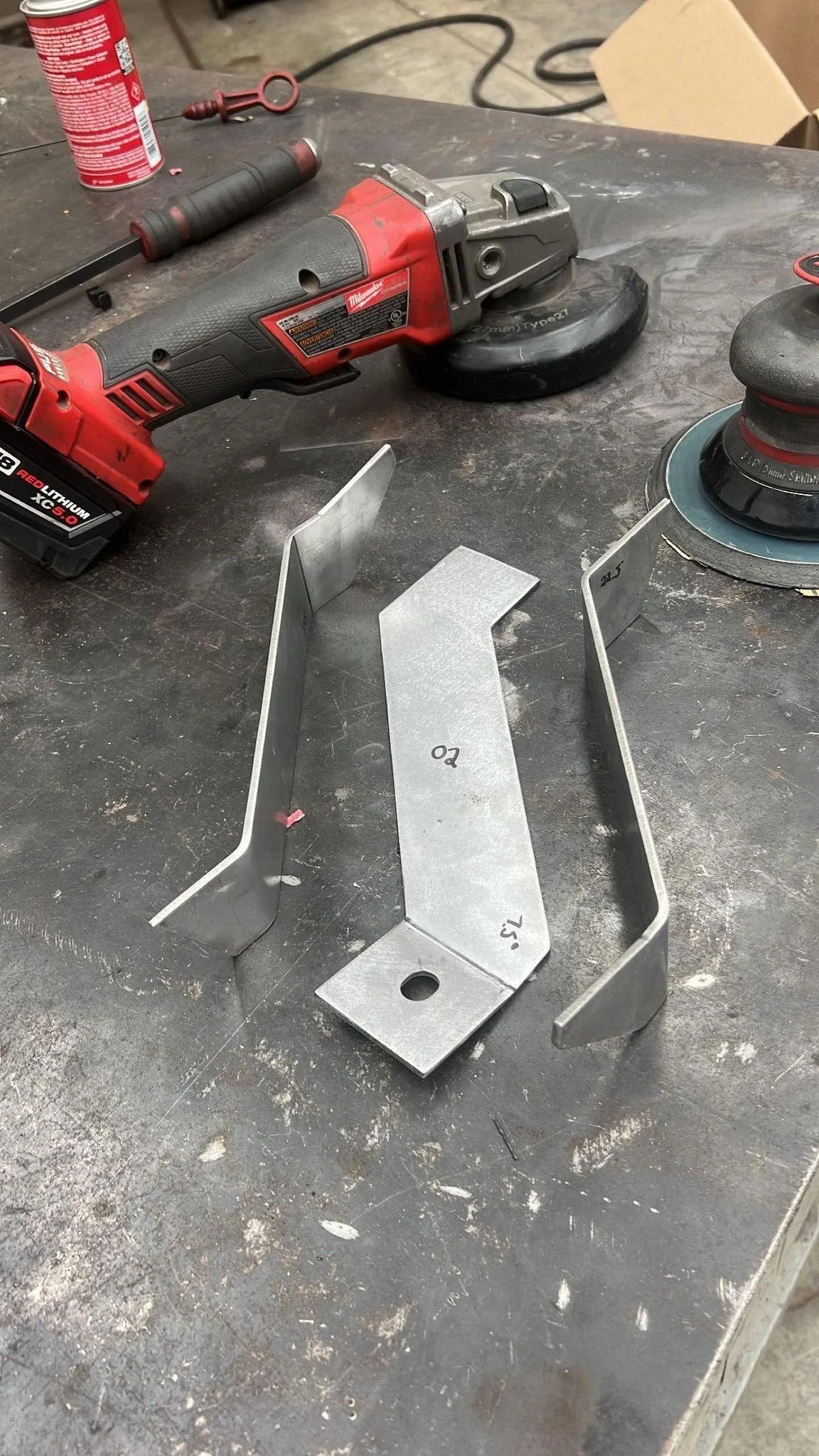
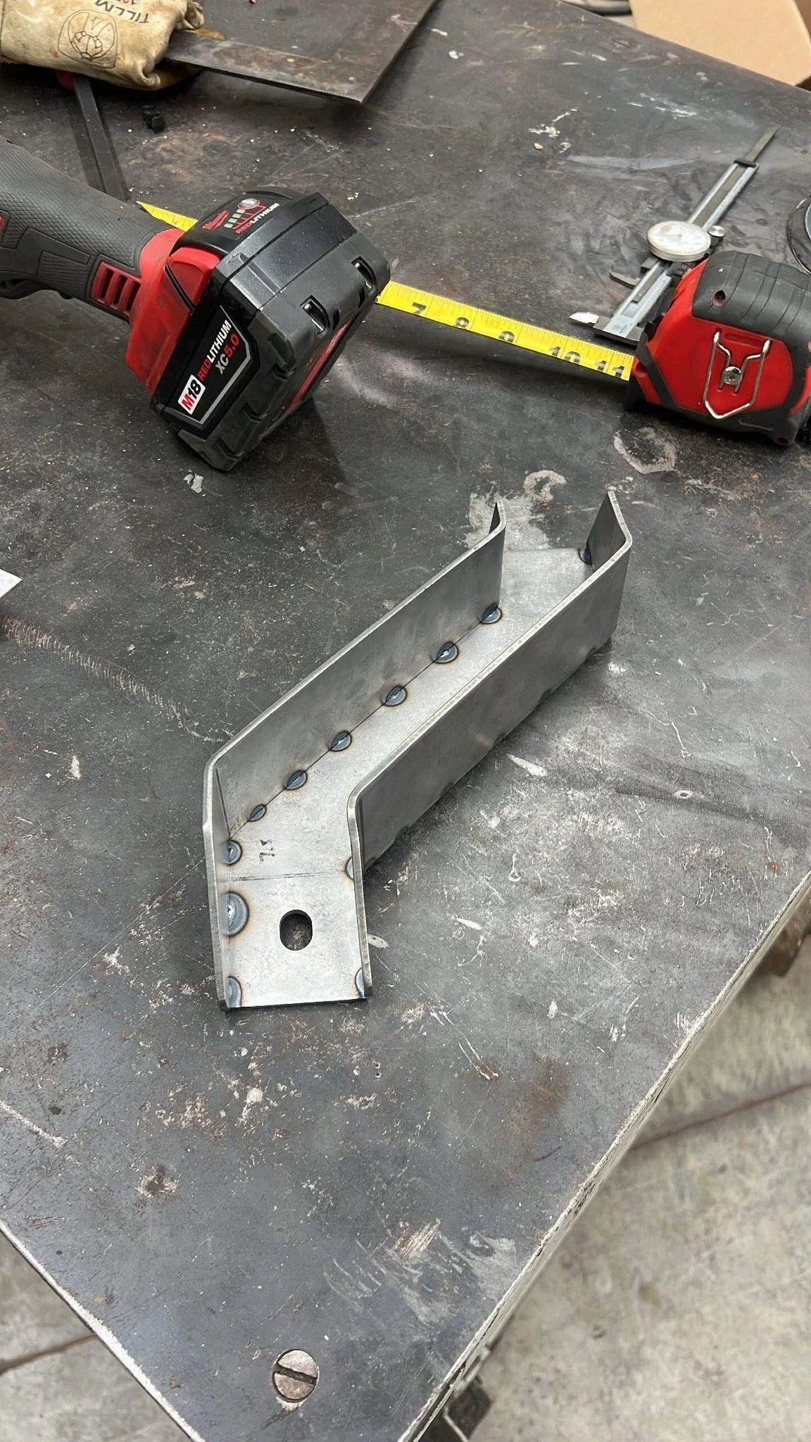
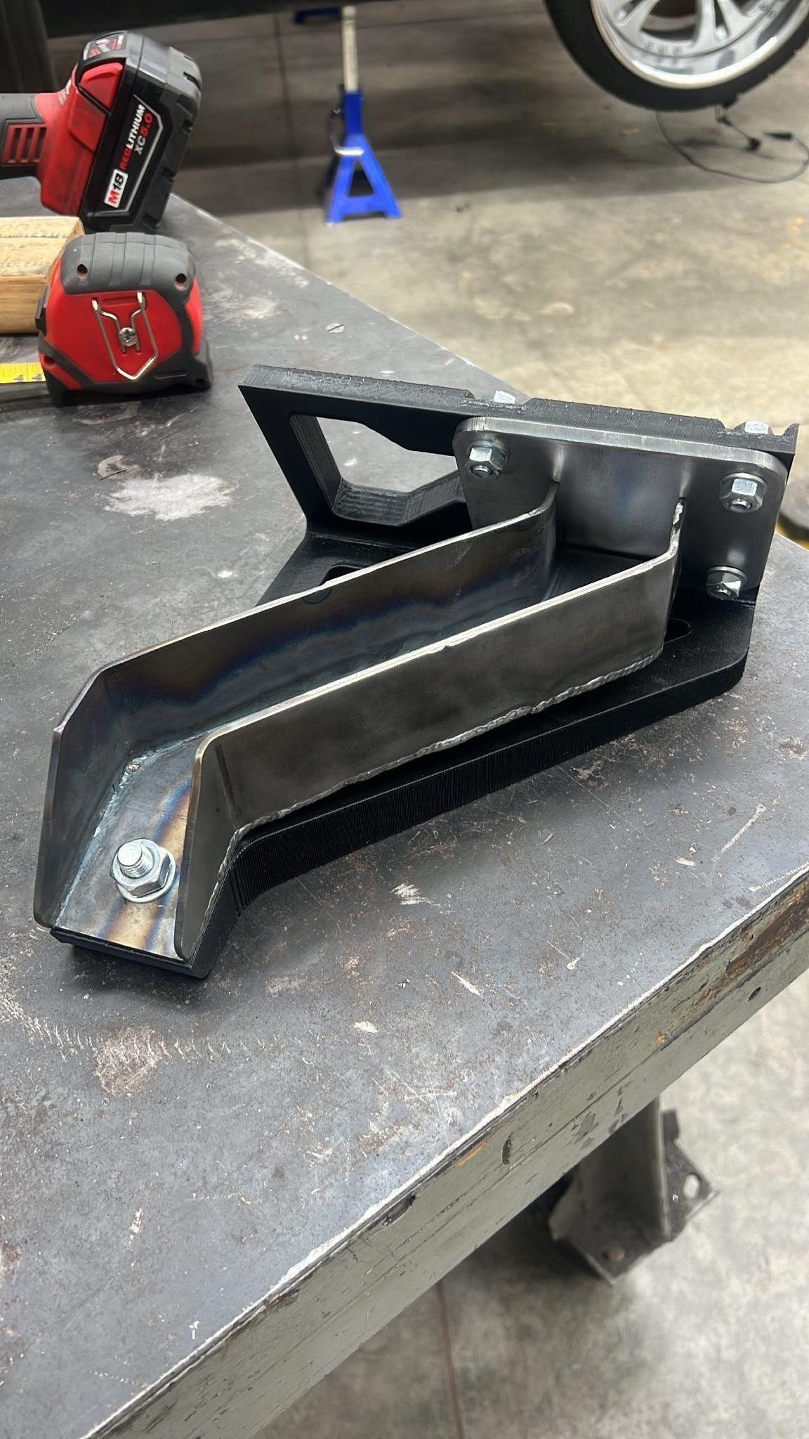
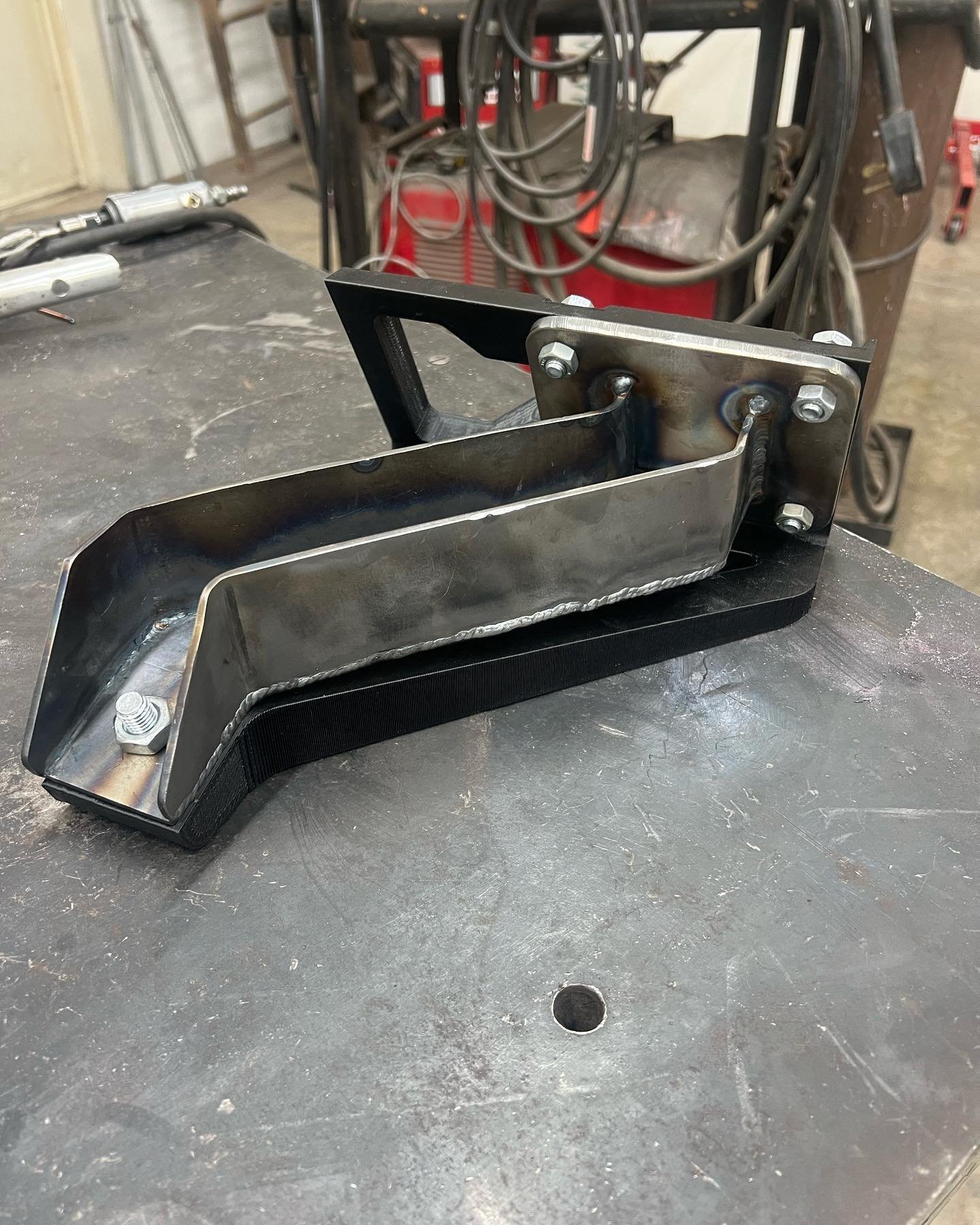
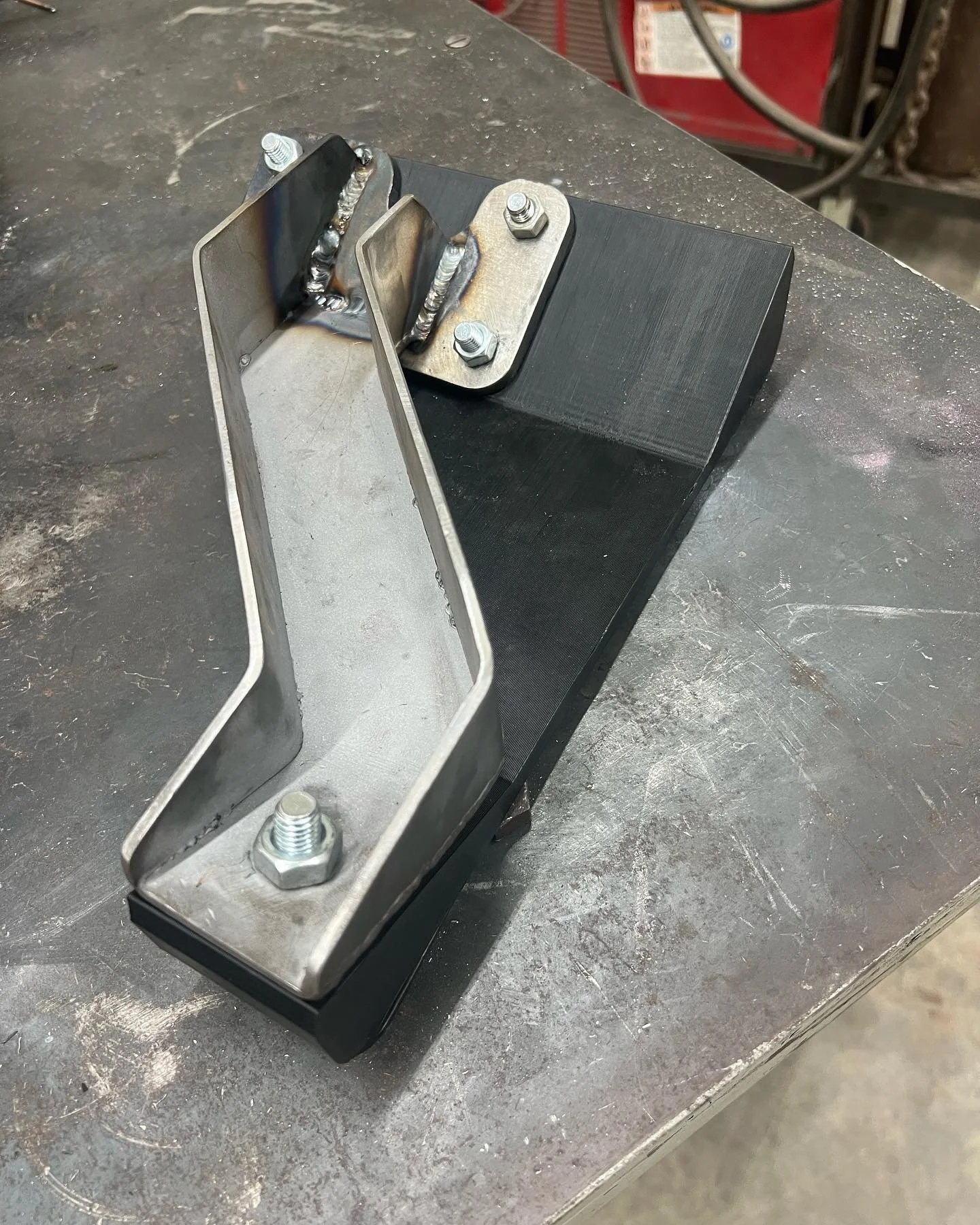
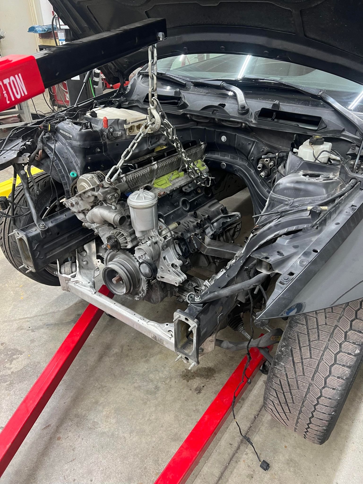
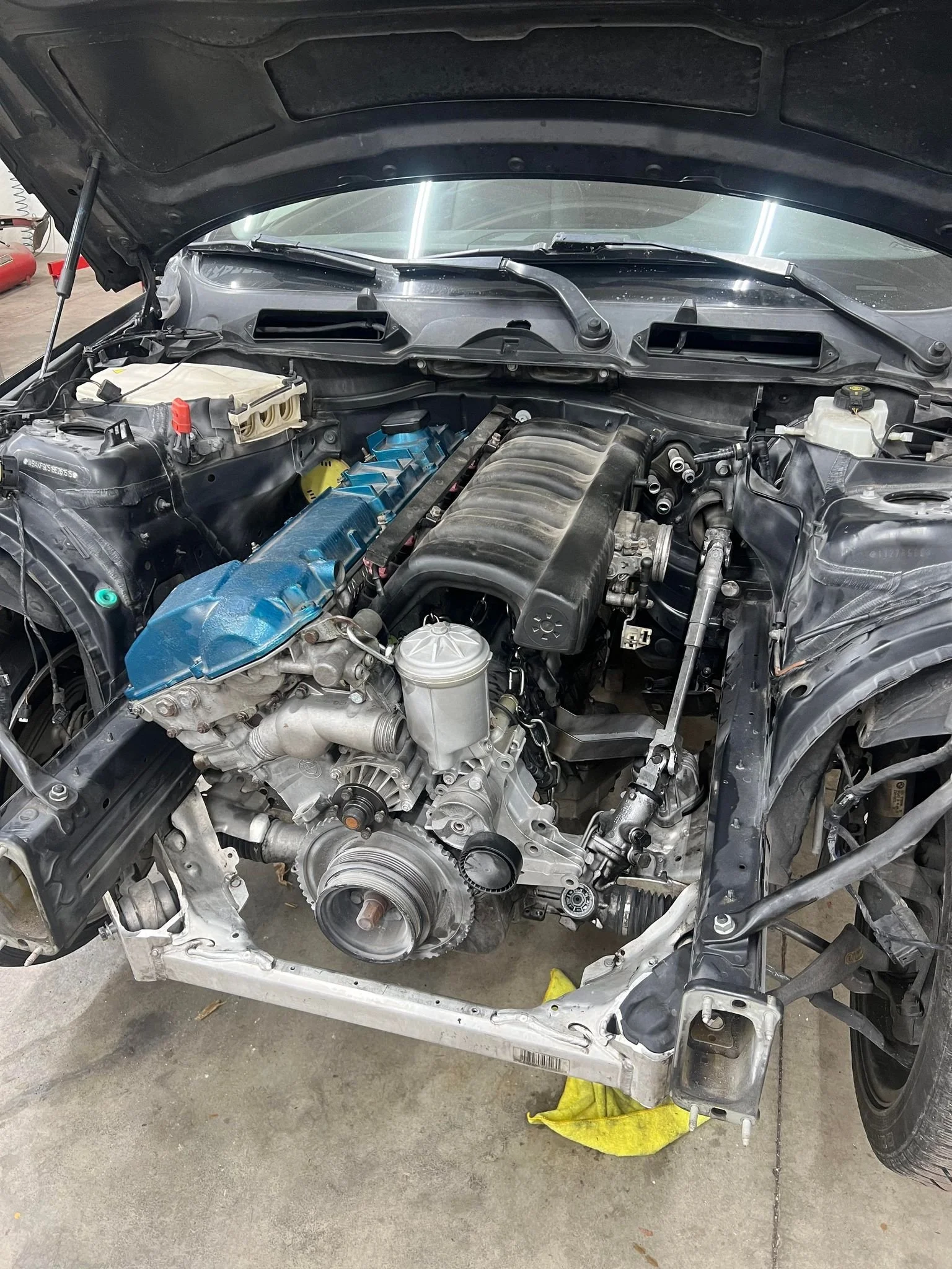
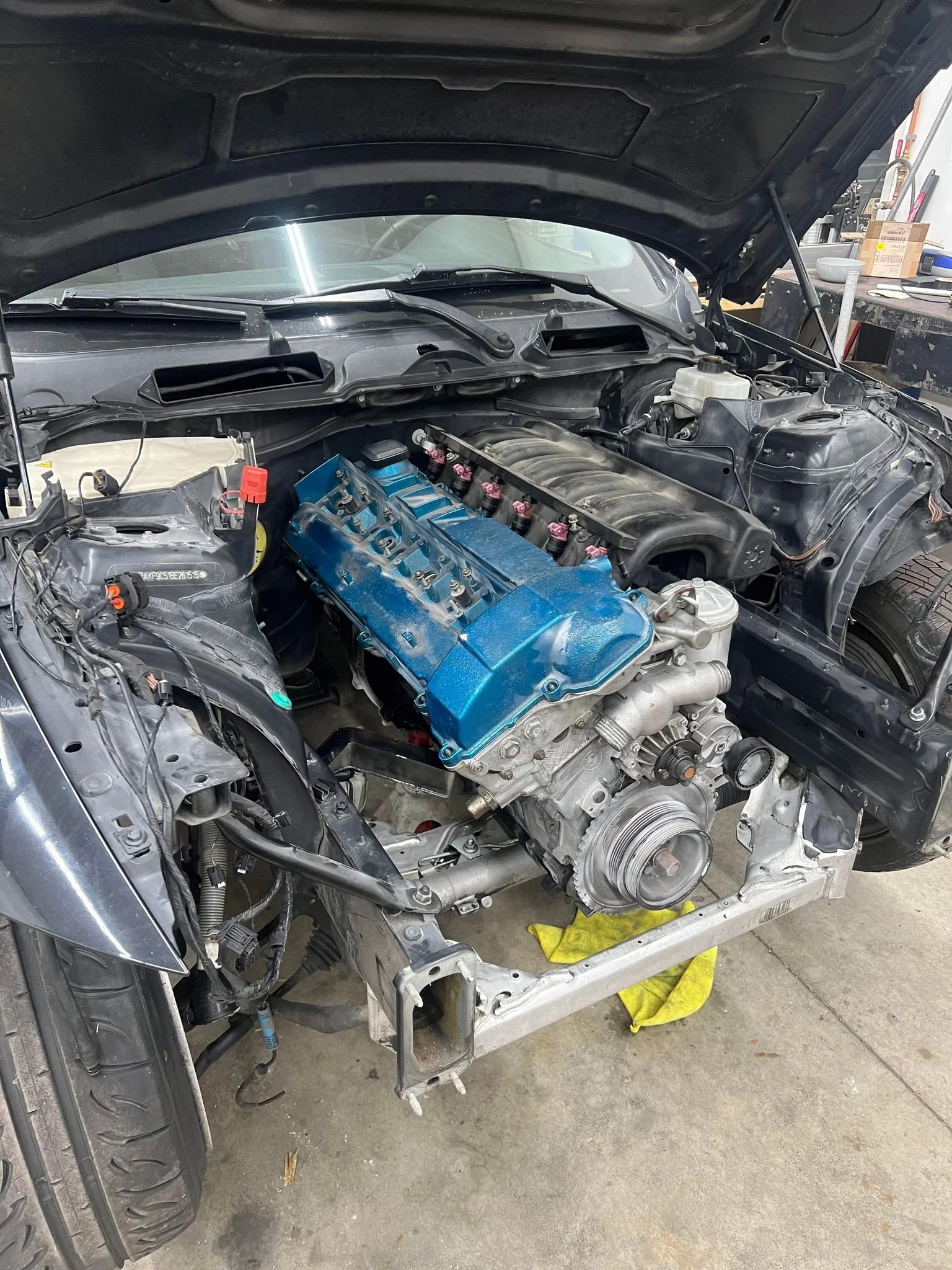
With the motor mount arms complete, it is time to bolt them to the engine and test fit. Just like the 3D model, the engine dropped right into place. After the initial test fit, the engine was removed to fit the transmission and placed back into the engine bay.
The process of taking a concept from the computer to real life has been extremely rewarding, and excites me to see what else this build and the future has in store has instore.
